Hydraulic Pumps

Hydraulic pumps convert electric/thermal energy into hydraulic power.
The main function of an hydraulic pump is to generate flow and pressure to drive hydraulic actuators, such as motors or cylinders.
Hydraulic systems are present in a big variety of applications, among which Agricultural (Harvesting machines and Loaders), Construction (drilling, piling machines), Earth Moving (Excavators, Dozers, Back-hoe Loaders), Marine and Offshore (Winches and Cranes), Utility Vehicles (Sweeper machines, Aerial Platforms, truck cranes), Industrial applications (Hydraulic Press), and much more..
Hydraulic pumps can be divided in two Main Categories:
• OPEN LOOP
o Gear Pumps (Internal / External gears)
o Vane Pumps (Fixed or Variable Displacement)
o Piston Pumps (Fixed or Variable Displacement)
• CLOSED LOOP
o Variable Displacement Piston Pumps
We will cover the various models and working principles in the following chapters.

OPEN LOOP – External Gear Pumps

hydraulic pump
hydraulic pump
Gear pumps are suitable for applications requiring medium-low flow rate and pressure values not exceeding 200 ~ 250 bar (3,000 ~ 3,500 psi). The design is simple yet reliable and compact, making it one of the most common components still in the market. Another advantage of the gear pumps is the price, making it a very cost-effective solution. However, gear pumps are not the ideal solution when dealing with very high flow & pressure and in those applications where high efficiency is required.
Gear pumps are available in a multitude of configurations, such as aluminium alloy or cast-iron body, a variety of parallel, splined and tapered shafts, different port configurations, single or multiple stage and customised designs.
A wide range of simple pumps and multiple pumps are ready in stock or available within a few business days, depending on the configuration required.

OPEN LOOP – Vane Pumps

Vane pumps can feature single or double eccentricity vanes.
The first one has a round stator and an eccentric rotor.
Fluid is transported around the periphery,between the stator
and rotor by the vanes, which make a half turn. In general,
pumps with singleeccentricity vanes are equipped with a displacement
regulator, which in the event that pressure is reached will reduce flowrate
and thus stabilise pressure. Pumps with double eccentricity
vanes have a round rotor and a shaft centred in relation
to the stator. The elliptical shaped track creates eccentricity.
hydraulic pump
Vane pump are energy-efficient, low noise, long lasting and compact.
The core of this pump design is the cartridge unit, which can be easily replaced after excessive wear and tear.
Basic symptom of wear and tear is the drastic decrease of volumetric efficiency when pressure increases.
The cartridge is made up of a rotor, vanes and inserts, a cam ring and two covers. The Rotor is connected to the shaft and is driven
by a prime mover (i.e. electric motor). As per the centrifugal force principle, once the speed increase the vanes
are pushed out against the cam rings, delivering oil from suction to pressure area.
Our Vane Pumps range goes from 8 l/min to 370 l/min @ 1,200 rpm.
We ensure perfect interchangeability with most popular brands, such as Eaton-Vickers, Parker-Denison, Bosch-Rexroth
and Caterpillar.

OPEN LOOP – Piston Pumps (fixed displacement)

hydraulic pump
Fixed Displacement Piston Pumps, Bent Axis Design are the perfect solution for heavy duty applications, where high pressure and high efficiency are required.
In this pump, the housing, cylinder barrel and pistons are inclined with respect to the output shaft. The angle may vary from 25 to 40 degrees. As the shaft speed increases, half the pistons suck oil from suction port and other half deliver the oil through the outlet port at high pressure, based on system requirements.

OPEN LOOP – Piston Pumps (variable displacement)

hydraulic pump
Variable displacement Load Sensing piston pumps have the exceptional feature to adjust both flow and pressure based on the system requirement. They are usually connected to a proportional valve.
As following the basic functions:

Stand-by (Zero Flow) Position

hydraulic pump
When the proportional valve is not activated, the pressure in the P line increases until it reaches the LS stand-by pressure. Usually this pressure is set between 14 and 30 bar, based on the application. In this scenario, the pump is on stand-by, delivering zero flow to the system. Power consumption is minimal.

Max Displacement (Full Flow) Position

hydraulic pump
The proportional valve is fully activated, sending a signal (LS signal) to the pump to deliver the flow. The swashplate is then pushed to its maximum allowed angle (usually 18 degrees) and the pump is at full displacement, delivering full flow.

Flow Control Position

hydraulic pump
When the operator moves the lever towards intermediate positions, the swashplate inside the pump is adjusted to meet the new required flow.

Pressure Cut-off (Zero Flow) Position

hydraulic pump
If the actuator (i.e. cylinder) reaches the end stroke and the proportional valve is still open, the system pressure builds up until reaching the pre-set value of the pump pressure compensator (PC). In this scenario, the pump swashplate is again activated and gets de-stroked to zero degrees (zero flow).
Important note: the relief valve on the proportional valve should be set at least 30 bar higher than the pump pressure compensator (PC) setting, allowing the PC to intervene first. I.e. if PC is set at 300 bar, the Proportional Valve relief should be set at least to 330 bar. This is to prevent power consumption and overheating of the system. The relief valve should intervene only in case of Pressure compensator PC failure.

CLOSED LOOP – Piston Pumps (variable displacement)

hydraulic pump
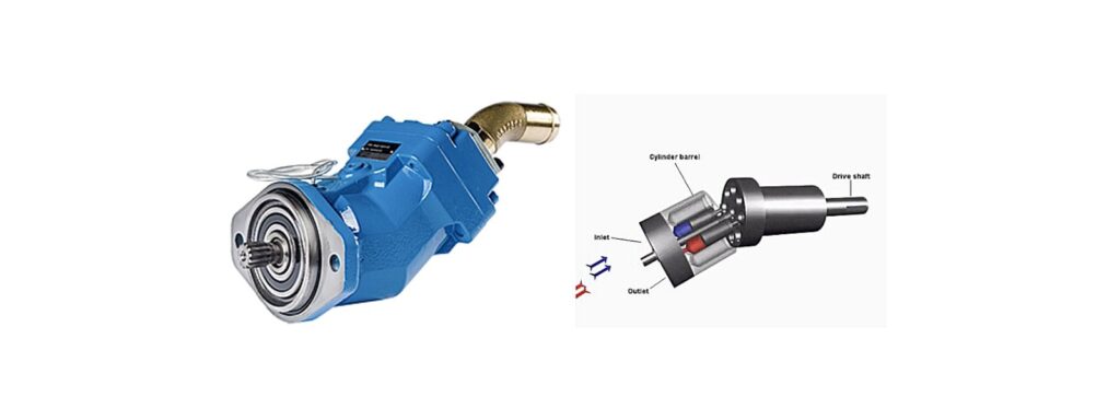
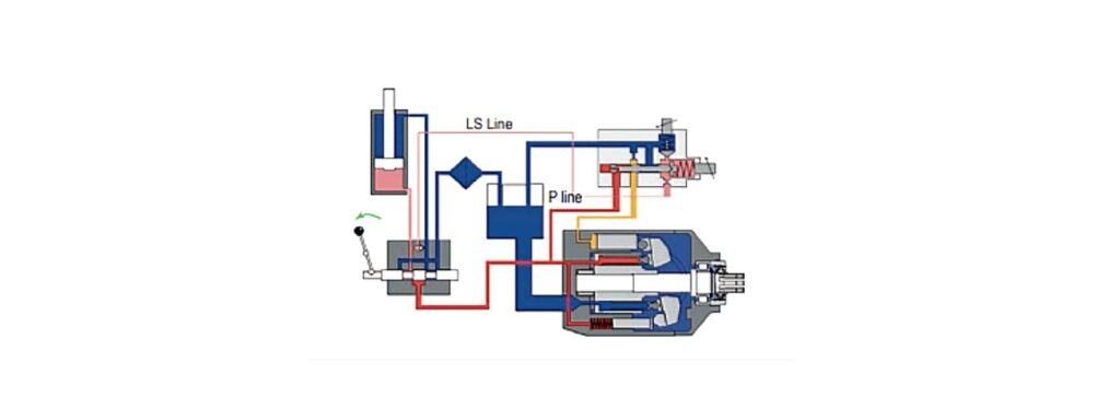
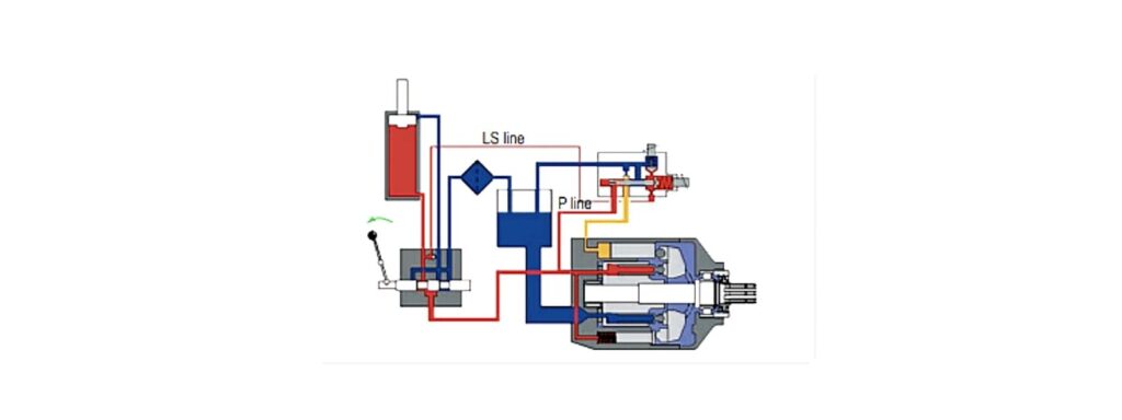
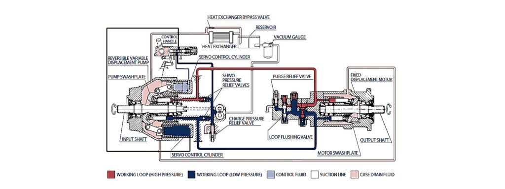
Variable displacement axial piston pumps are designed for use in in closed circuits, connected directly to motors. As following a basic schematic of an hydrostatic transmission with variable displacement axial piston pump and a fixed displacement axial piston motor.
hydraulic pump
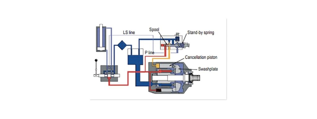
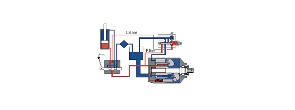
The displacement is adjusted by means of a servo-control and an internal swashplate. The closed loop design allows the swashplate to incline infinitely between -18 degrees and +18 degrees.
The zero-degree position is the zero flow stand-by position, where the motor is not moving.
Various controls are available to adjust the flow (hence the speed) of the motor: manual lever operated, electric on/off, electric proportional, automotive, etc.
Closed loop pumps have a built-in charge pump that keeps the closed loop ring filled of oil, keeps a positive pressure in the main circuit (usually between 20 and 30 bar) and provides pilot pressure to the servo-control. Most pumps are supplied with maximum pressure relief valves, even though in some cases the valves are installed on the motor side (i.e. in concrete mixer systems)
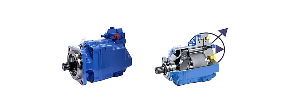
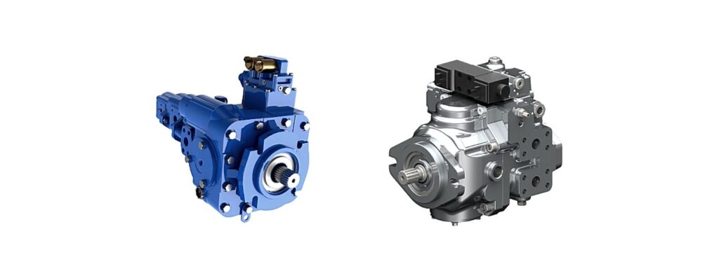
Closed Loop pumps can be configured as single or tandem version and can have several through drive options, i.e . to fit auxiliary gear pumps.
Closed loop systems are the ideal solutions for mobile vehicles, such as harvesters, concrete mixers, loaders, compactors, etc.
Our specialized team will be able to recommend the right pump and control for your applications.